
BCIT Physics Department
- To show that the direction of induced current depends on the direction of a coils motion in a magnetic field.
- To show magnetic damping of a coils oscillations.
 |
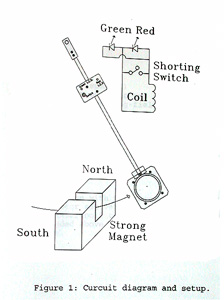 |
When the circuit switch is OFF the coil output goes to the diodes with current flowing through whichever diode happens to be froward biased. For the geometry shown in the diagram, the red diode illuminates as the coil approaches the magnet from either side. This indicates clockwise current in the coil as viewed from the front. The green diode illuminates as the coil swings away from the magnet.
In this case current is counter clockwise.
For the induced voltages produced, the diodes only allow a small current to flow, hence damping is not evident.
When the switch is ON the coil output is shorted. The induced current will now be large enough to cause a strong damping effect on the coil's oscillation.