
BCIT Physics Department
- To illustrate the behavior of inductors, capacitors and resistors in DC and AC networks.
To introduce the ideas of inductive and capacitive reactance and impedance.
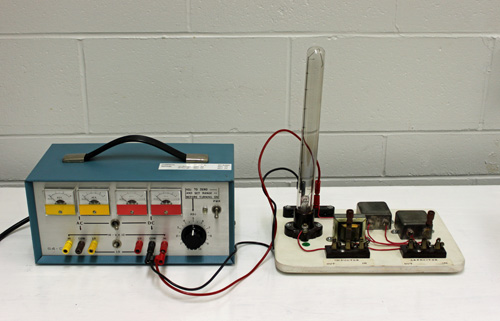
The R, L and C components are connected in series with a shorting switch across each component. The series-connected lamp serves as an indicator of current flow and magnitude, as well as providing a load for the network.
With the power set to DC the response to R, L and C is individually observed and inferred from the lamp brilliance. Then, with the power set to AC, similar observations are made. Concepts of inductive reactance, capacitive reactance and impedance are introduced and observed.